Page 1 of 1
Posted: 04 Sep 2010, 19:25
jigebren
I'm currently trying to write another tool for re-volt. This one would automatically create the .hul file from a .prm/.m file, which is one of the things that lacks the most when creating our own model or car body. I had this idea in mind a long time ago, but my previous attempts all came to nothing because of the difficulties I ran up against...
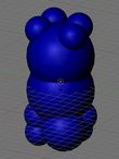
Now I've found I can skip some of these difficulties, so I was able to get some results. Here is the set of spheres filling he hull automatically generated (both hull and spheres) by my tool for the bottle model:

For info, the .hul file is composed of one of several convex hull(s) and of a set of spheres. Both are used to detect collisions (with the world, or with cars, or simply between objects).
I'd just like to clear up some points:
- Here I'm visualizing the result with Blender, but this tool doesn't have (and will never have) neither any visualization feature, nor any realtime HUL editing feature.
- I wrote my own algorithm to generate the Convex Hull, so while it is accurate, it is far from being as fast as possible.
- To understand how .hul file are used and what limitation the
convex term implies, you have to know what a
Convex Hull is.
- The procedure used to fill the Convex Hull with spheres (the blue spheres above) is
very basic (it would also be very hard to get something perfect...). But playing with the resolution (the minimum size allowed for spheres), I think I can get descent result (as you can see above).
- I don't know if I'll actually finish/release it one day.
Posted: 05 Sep 2010, 02:19
Huki
That is great news. Since i don't know much about hulls, i have just one question. How do you think Acclaim generated hulls?
Posted: 05 Sep 2010, 03:29
urnemanden
I would be really excited about that tool. It would allow custom models to the max, small stones you can drive into and push and new weapon designs.
Whether you choose to work further on the hul converter or not, good luck!

Posted: 05 Sep 2010, 06:01
jigebren
I have improved a bit the procedure used to fill the Convex Hull with spheres, mainly for regular shape like boxes.
Filling re-volt "Packet.m" model, with previous code:
With new code, it's a lot better:
I have also tested in the game with a generated hul for the "bottle.m" model, and it worked nicely...
huki wrote:That is great news. Since i don't know much about hulls, i have just one question. How do you think Acclaim generated hulls?
I have no idea... The hull has to be computed, but perhaps they tweaked the spheres by hand, I don't know, maybe they were also automatically computed.
But I'm quite sure for example that the mouse hull is buggy, as it is internally dupplicated or something like that.
Posted: 05 Sep 2010, 20:32
sebr
Posted: 05 Sep 2010, 23:00
KDL
that's nice
I was going to make a hulgenerator in 3 days for my project Car::Load, but guess someone was here before me

looks promising, keep up the good work! and of course we hope you good luck from the deep of our hearts (we=Revolters)
_
@Huki, if you look at Re-Volt's source [rv1.zip by ADX], you'll find "CarConv" (I think that's the way where acclaim dudes converted cars (from their .p3d 3D homemade modeler format to Re-Volt formats)
Posted: 08 Sep 2010, 07:32
jigebren
I think this project is taking good shape.
I have improved a bit the sphere filling procedure, trying to make it a bit more evolved/smart. I'm now using a totally different way to look for optimal filling, which was very slow at first, but I think I have found a trick to make it far more fast (which doesn't mean at all that it is actually fast...).
And we will now be able to define
excluding hull. It's not something that will be saved in the final hul file, it's just to allow a better tweaking of the collision data by defining areas that won't be filled with collision spheres.
Here for example, I'm filling the Col. Moss body, excluding the area defined by the bottle.m model. There is a lot of sphere used (50), which is of course far too much, but it was for testing purpose:

---
Funnily, that page was already opened in my browser when I read your message.
Even though it's now missing some stuff and would need a little update, I respect a lot ali's page, as it was probably the starting point of my interest in re-volt breakdown...
@KDL
Thanks. And I think I have avoided you some pain, as automatically (and properly) filling the hull with collision spheres is quite more complicated that I expected at first sight (and at second too

)...
Posted: 11 Sep 2010, 06:48
jigebren
Some news about this project.
It's quite close to be made public, I think. Maybe tomorrow if I have time to pack/upload it, or at least in a very few days.
I have made a lot of attempts to try to find a good position for the collision spheres, and I have spent quite a lot time to achieve to find a calculation that would not give an inconsistent result with a very ideal/regular shape like the packet model. It was not very easy, or maybe I'm too dumb to make it more quickly...
And also, as my own calculation to find the convex hull was way to slow, I have added the possibility to use a very good
external tool (qconvex) that does the job in an awfully more efficient way. It speeds up the process a lot, mainly for model with lots of vertices.
Here is a screeshot of prm2hul, so that you can appreciate the nice and modern design of this application. Well, I hope it will make you wait patiently until it is finally released...

Posted: 11 Sep 2010, 14:01
urnemanden
Looks quite nice, but also quite advanced. I hope you will write something about the parameters in the readme tho, because I guess I cannot see the result of the conversion, only feel it while driving into it.
Posted: 11 Sep 2010, 20:42
jigebren
It's done, you can now download it from my webpage.
But I have no time to add more detailled instruction/documentation about it this WE.
Just for you to know, the generated hul file will contain
one or more convex hull (only the planes data, as edges and vertices are not used anymore by re-volt), and
a set of several spheres. You can set the number of spheres in this tool, but there is no setting as far as the convex hull is concerned, all is automatic.
Don't modify the Advanced settings. But you can play with the number of spheres.
And by looking at the Log infos, it's possible to get an idea of a well balanced number of sphere to use.
I'll explain it in more details latter, but several files can be used as input, as they will be merged in one single collision file (it allows to have several convex hulls for one model).
For info, for an object like the bottle.m model, the
convex hull is used for collision with cars (and probably with other objects too) while the
spheres are used to detect collision with the world.
Posted: 11 Sep 2010, 21:59
zagames
Great work! This will come in handy with the Arctic mod.
Posted: 13 Sep 2010, 04:40
hilaire9
Question:
Can these custom .hul files work in tracks as collision data
for custom models?
If so, were do you place the custom .hul files so they are detected?
Many in-game models do not come with .hul files (i.e, Planet models).
Posted: 13 Sep 2010, 20:05
jigebren
hilaire9 @ Sep 13 2010, 12:10 AM wrote:Can these custom .hul files work in tracks as collision data
for custom models?
The .hul file can be used for instances (the .prm in the level folder), though I don't know exactly when using a .hul or a .ncp is more pertinent (well, it seems more or less clear that .hul are used for moving objects which you can interact with, and which can collide with the world, while .ncp are used for still objects, or object like the train that you can collide with, but can't interact with).
Hul file can also be used for models (in the "models" folder, in case you customize them), but only for models that already have collision data (like bottle.m or trafficcone.m). As I said just above, I don't think that using a .hul for a model that had a .ncp file (like dragon1.m) could make any sense.
But you can't add collision data for all other models, which don't already have a .ncp or .hul file (like planets, copter, etc.), because collision for these models is directly deactivated in re-volt binary (and not reactivable).
If so, were do you place the custom .hul files so they are detected?
Always along with the corresponding .prm/.m file, that is to say in the "#\?????" folder if you use custom models.
Posted: 14 Sep 2010, 09:55
Huki
I tested prm2hul with some cars and they work nicely. With the default settings the hul file size is a little larger though (probably uses higher precision), but i think it's good. Thanks for adding yet another missing tool for the track/car makers.
Posted: 15 Sep 2010, 01:00
krisss
Hi!
Thank you, Jigebren again!
This is so good and easy to use tool...
Posted: 18 Sep 2010, 13:04
nero
jigebren wrote:It's done
WOOHOO!!!
Posted: 24 Sep 2010, 12:06
Citywalker
urnemanden @ Sep 11 2010, 09:31 AM wrote: Looks quite nice, but also quite advanced. I hope you will write something about the parameters in the readme tho, because I guess I cannot see the result of the conversion, only feel it while driving into it.
because I guess I cannot see the result of the conversion, only feel it while driving into it.
Jigebren, you could make the log output a bit more detailed.
Instead of this:
08:10:03. Sphere 1 covers 27.1% of the hull volume. (72.9% remains).
08:10:03. Spheres BBox is covering [x: 88%, y: 64%, z: 43%] of the Hull BBox.
08:10:03. Sphere 2 covers 26.2% of the hull volume. (46.7% remains).
08:10:03. Spheres BBox is covering [x: 89%, y: 75%, z: 78%] of the Hull BBox.
To be something like this:
08:10:03. Sphere 1 covers 27.1% of the hull volume. (72.9% remains).
08:10:03. Sphere 1 coordinates: x:-20, y: 55, z: 0, radius: 12
08:10:03. Spheres BBox is covering [x: 88%, y: 64%, z: 43%] of the Hull BBox.
08:10:03. Sphere 2 covers 26.2% of the hull volume. (46.7% remains).
08:10:03. Sphere 2 coordinates: x:20, y: 55, z: 0, radius: 12
08:10:03. Spheres BBox is covering [x: 89%, y: 75%, z: 78%] of the Hull BBox.
I could visualise it better in my head then, and someone could use this output for a machine visualisation eventually.
Posted: 15 Oct 2010, 07:17
jigebren
I have finally updated this tool, sorry for the delay CW...
No big changes, but along with the added sphere coordinates in the Log, there is a new option to copy in the result in the clipboord. It is mainly intended to be pasted in a spreadsheet program (to draw curves), but it may also be used by an external tool to display the spheres...
I wasn't sure if I have to let the experimental overshot feature (I'm not even sure 'overshot' is the most appropriate term), but as it would be more work to remove it, and as it could perhaps be useful in some cases (mostly very thin object), I'm letting it for now.
Changelog wrote:* Rel.10-10-15
Mod: The log layout now include each sphere coordinates and radius.
Add: Allow overshot: (experimental, mostly intended for thin objects)
Allows spheres to go over the CHull limits by a given percentage (100%
corresponds to the smaller side of the convex hull's bouding box).
Default value of 0% should be appropriate in most case.
Add: Copy result to clipboard:
Fills clipboard with the tabulated log data. It can then be easily
imported in any spreadsheet program (like eg. OOo's Calc or Excel), so
that curves can be drawn to visualize the progression of parameters versus
the number of spheres (it can be used to determine the optimal number of
spheres to use for a given model).
Prm2hul can be downloaded
from my website.
(Refresh your browser's cache with F5 key in case of 'file not found')
Posted: 15 Oct 2010, 13:46
Citywalker
Yeees! Yes, yes-yes-yes-yes. This is even better than I thought, because you already tabulated the data before sending to clipboard. I was able to easily make 2 charts in Excel, showing the collision spheres.
I uploaded it, so others could use it as well.
https://rcpt.yousendit.com/968572587/6f ... 4205777703
Now it’s easy as 1-2-3:
1) Create the hull in prm2hul.
2) Simply paste its clipboard dump into the prepared spreadsheet.
3) The charts automatically show the spheres as top view and side view.
It‘s even very easy to check which sphere goes where, by just temporarily deleting the radius value in the table (Undo (Ctrl+Z) gets it back).
Only one caution regarding regional settings in windows: prm2hul uses point as the decimal mark, but e.g. in my country the Excel uses a comma there. But that’s a matter of simple search-and-replace.
So, the hull can now be visualised <cue trompets>

> sorry for the delay CW...
Nooo problem, as long as it got done
Btw, Jigebren, you could include it in the prm2hul package if you want, the yousendit link will expire in a week...
Posted: 16 Oct 2010, 01:07
jigebren
About the regional settings, I have the same comma/point issue in my country too. But instead of using search/replace to fix it, I would rather recommend to edit the regional setting of the cells in the spreadsheet.
By the way, I have put your Excel file directly on my website for now. Thanks for it.
I'm also providing a similar pre-formatted Open Office file, maybe you should take a look. There is no issue with the decimal point, and it can be used without modification for up to 50 spheres (which is far more than needed but could be usefull when testing).
All is available
here.
Posted: 16 Oct 2010, 08:01
Citywalker
Jig, a humble correction to your very detailed OO spreadsheet: the side view is from LEFT side, not right side. <friendly smile>
And I think I'll keep my spreadsheet, because it shows the actual sizes of the spheres and that's more useful than point centres. The visual effect of the filled hull space is lost with point centres and I wouldn't know which spheres are superfluous without seeing where the sphere edges meet.
Posted: 16 Oct 2010, 18:26
jigebren
Oh, I was quite sure it was the right side... I'll check it, thanks for informing me CW.
Can you post (or email me if it simpler) an screenshot of your spreedsheet?
I think I just can't have the sphere size drawn in Open Office...
Anyway, I have added the display of spheres only after having seen your idea, but the main objective of this file for me was first to have the result values drawn against the number of used spheres, to be able to determine the optimal number of spheres to use for a given model.
Posted: 16 Oct 2010, 19:18
Citywalker
Well, the main objective for both of us is to determine the optimal number of spheres, we just have different approaches. You like the technical view of a diagram, I like the visual view of actual spheres. Whichever works best for anyone...
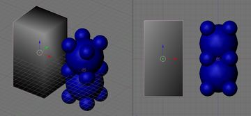
The screenshots are there, with the stock Panga (Panda Bear) as 50 spheres and as 30 spheres:
https://rcpt.yousendit.com/969341145/93 ... 34821556fc
Please note that the graphs are usually under each other, so as not to cover up the sphere values, but they wouldn’t fit into the screenshot this way.
With MS Office, the graph type is called “Bubble Graph” or something.
Posted: 25 Oct 2010, 18:36
jigebren
About "Bubble Graph"
Thank CW for informing that the graph type is called "Bubble Graph". Funnily, it has just been added in the very last release of OpenOffice (v3.2), and I was using the previous one. After updating, I can now create bubble graphs too.
But it's not as good as it seems... You have to use the displayed information very carefully. It is very likely that the graph does not show properly the radius of the sphere, as well as the position of the spheres intersection. It's a bit long to explain in detail, but there is 2 probable issues:
- the graph will be inconsistent if the X and Y axis scale are not exactly the same. I mean that one unit on both axis should output exactly the same lenght on the screen (otherwise ellipsis should be displayed to be correct, but Bubble Graph only draws spheres).
The only way I'm thinking of to be sure that the axis are scaled properly is to manually set the same Min/Max range for both X and Y axis (for example, from -100 to 100), and to be sure that the displayed graph is a square (not a rectangle).
- Even if you respect the above condition, you have no direct control on the sphere radius scale (at least in OOo, in don't know about Excel but it's likely to be the same). What I mean, is that the sphere radius scale is chosen automatically to fit the graph, so for example if you divide all sphere radius by 10, you'll see that the graph output will remain the same (because the scale will be adjusted automatically, the bubble radius won't decrease by 10).
To conclude, I was thinking about updating my OOo template to use Bubble Graph, but I think I won't do it, as it is far too open to misinterpretation.
Posted: 26 Oct 2010, 14:16
Citywalker
Mmm-kay... the settings of the bubble graph should be studied, then.
Anyway, I’m currently using it in its distorted form for intuitive checking, i.e. if the front of a car sinks into wall with 15 spheres, then I put some 40 spheres into the graph and then start deleting them, until some crucial-looking spheres in the front of the car start disappearing. At that point I know that I shouldn’t reduce the number of spheres any more. It works reasonably well this way.
Posted: 26 Oct 2010, 18:12
jigebren
Citywalker @ Oct 26 2010, 09:46 AM wrote:[...] if the front of a car sinks into wall with 15 spheres, then I put some 40 spheres into the graph and then start deleting them, until some crucial-looking spheres in the front of the car start disappearing. At that point I know that I shouldn’t reduce the number of spheres any more. [...]
This result could be directly found without having to delete spheres one by one, by proceeding that way:
Look at the
BBox coverage evolution on the chart where data are plotted against the number of spheres (the chart at the top-rigth on
this screenshot). Each time there is a sharp rise one one curve, it means that the last sphere adds significant data on the given axis (I understand that this method sounds far less intuitive, but it's quite easy once you're used to it, you just have to figure out what the plotted data stand for...).
For example, on the above screenshot, we can see that the sphere #9 noticeably increases the collision size on the Z axis. Then there is just a little increase on X axis with sphere #17. We can conclude that using more than 9 spheres is likely to have no real benefit.
For info, I have to clear up what is
BBox coverage evolution:
If you take the set of spheres in 3D, we're looking for the smallest Box that englobe all spheres. This is what we call the
Bounding Box (BBox).
Each time a sphere is added, the BBox size may increase if the sphere is big enough or has been added at the edge of the current BBox (but if a little sphere is added quite in the center of the current spheres set, it's likely that the BBox size will not change).
Posted: 26 Oct 2010, 18:27
urnemanden
Does the use of the hull file differ after which racing mode you use? For example it would most likely make sence to me if the Bbox was used in Console mode, since it's way harder to collide with each other compared to simulation mode.
Posted: 26 Oct 2010, 19:22
jigebren
>> Does the use of the hull file differ after which racing mode you use?
Yep, it does indeed. Though I can't tell in details how, it seems that Simulation mode uses both the CHull (Convex Hull is a set of planes) and the set of spheres, and test Wheels separately, while other modes only work with the set of spheres, and even other simplifications in console and kid modes...
Posted: 26 Oct 2010, 21:10
Citywalker
jigebren @ Oct 26 2010, 01:42 PM wrote: This result could be directly found without having to delete spheres one by one, by proceeding that way:
But:
a) then I would specifically have to look at the sphere co-ordinates and still imagine it in my head, to know whether the sharp rise in one curve is due to a sphere in the middle of the roof or in the front end of the car. Seeing the sphere visually disappear and appear is easier on the bio-GPU
And sometimes it’s two little spheres in the front corners that keep the front end from sinking into the wall by those ugly two centimetres, so that sharp rise is nowhere to be seen.
So it’s still that same old “whatever rocks your boat”. Let’s keep both approaches available, because more variety means more people being comfortable using the tool.
Btw, an important note: the body offset in the parameters.txt _must_ be 0, 0, 0 to use autohulling. That’s something that could be overlooked. I did overlook this until a car seemed to go nowhere and spun its wheels in the air... :/
[Edited to remove double quoting...]


